Billet Motor Mounts and Supports
- Dec 4, 2024
- 3 min read
Updated: Mar 25, 2025
This project was for a motor upgrade test on Orbis Electric's McLaren MP4-12C platform. We needed to replace an OTS electric motor inside our planetary gear hub assembly with a different model, while reusing as much of the original housings as possible. This was so that the performance of the new motor could be assessed with minimal machining investment, and also to inform design choices for the dedicated new motor housings.
Since the new motor was shorter axially and constrained differently, runout of the input shaft was a risk. I decided to approach this solution with two parts: a primary mount, and an input shaft stabilizer to minimize deflection.
This larger X-shape is the primary mount. The outer features are dictated by the existing custom motor housing which it will be attaching to, and the interior mounting pattern is driven by the new motor, as well as coolant and electrical passthroughs.


This thinner component is the input shaft stabilizer, which I designed to accommodate a small press-fit bearing, mated to the output shaft of the motor, to support its rotation. Again, the outer arms fasten to the gearbox housing, and the center supports the motor.

This video shows the bearing installed, spinning with the input shaft from the motor. To clarify terminology, this input shaft is the driven shaft directly attached to the motor, but is 'inputting' into the planetary gearbox. The output shaft in this case refers to the final hub output from the planetary case.
To assemble the adapters and install the new motor, I had to begin with a full removal and teardown of the McLaren's rear drive assembly.

To install the primary mount, I had to manually cut out the previous bracing, which would have it's rigidity restored by these new pieces.


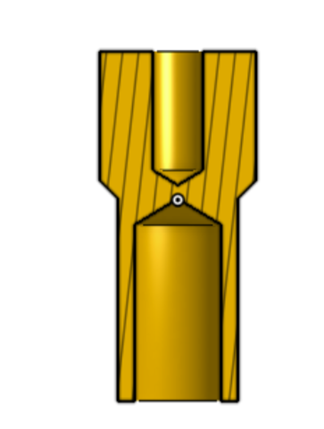
The following image shows the input shaft stabilizer, which locates its center on a round lip in the gearbox case.

With the primary mount and motor attatched, the assembly can be mounted back onto the McLaren's suspension. It is shown here without the input shaft installed.

Another challenge for this design was routing the power leads to the motors with appropriate clearances, and allowing for recommended bend radii. The motors being installed had permanently mounted lugs design to bolt into corresponding wire lugs running parallel to the axis of the motor. That was impossible to accommodate in this application with the upright assembly in the way. To address this, I designed cylindrical solder-cup lugs, that could be easily machined on a manual lathe. These featured an internal thread on a flat face opposite the cable side, so they could be bolted directly to the lugs, and run axially away from the motor without making any bends.
I assembled these cables myself, heating the lugs with a torch to melt the solder, then inserting the stranded cable which had been stripped to a precise length and covered in flux to assist with adhesion.
I then covered the entire lug with heavy duty heat shrink, and trimmed the excess flush along the edge of the lug, creating a fully insulated cable right up until the contacting face.
To relieve any tension on the lugs, and keep the cables routed securely, I designed a 2-peice plastic clamshell retainer, which bolted directly to by motor mount, and snugged onto the cables as it was being secured to the mounts with the same hardware.


I repeated this process for both sides, and subsequent testing indicated proper gearbox alignment, with expected performance.


Comments